Before 1960s the design criterion of substation earthing system. To connect the bimetallic conductive elements of an electrical appliance or installations to the planet ground is termed Earthing or Grounding.

Chapter 6 Earthing System Ppt Download
Articles GroundingBonding Telecommunications.

. Our technicians ensure all measurements are correctly taken and interpreted so that the true resistance of the earthing system can be accurately determined and verified. Earthinggrounding design is a safety-critical component of the HV power system. Today we are going to discuss the design of substation earthing system.
Connection between any circuitequipment and the earth. Tool for design of earthing system in low voltage installations. I Lightning and short circuit.
BS 7671 lists five types of earthing system. Preliminary layout design is to be conducted after deciding the type. Earthing system is designed followed by electrical system required and the applicationIt have different earthing system for each electrical application such as consumer.
Table 1 GPR and grid resistance for different earthing systems. Starting with Case 1 and adding 2 additional 20 m long mesh conductors installed in the form of cross the GPR decreases by 637. Earthing PRESENTATION BY.
Strip or Wire Earthing. The connection between electrical appliances and devices with the earth plate or electrode through a thick wire of low resistance to provide safety is known as Earthing or Grounding. Important formulas for Designing a Substation Grid Earthing System.
In this method of earthing strip electrodes of cross-section not less than 25mm x 16mm 1in x 006in is buried in a horizontal trenches of a minimum depth of 05m. Categories Power System Basic Electrical Circuit Breaker Electrical Relays Generation Substation Switchgear Transformer. All exposed-conductive-parts of an installation are.
In this series Earthing Design we take the lid off the design process from start to finish to demystify and bust a few of. Earth resistance measurement is essential to accurately determine that the installed earthing system meets the anticipated criteria laid out in the initial design. The earth system must protect the occupants prevent direct damage such as fire flashover or explosions due to a direct lightning strike and overheating due to a short-circuit current.
40 mm Ø GI CI Perforated pipe duly fitted or welded with base plate and 50 X 6 mm flat termination taken on top for equipment earthing as shown in drawing. If 6 further 20 m long conductors are added to form the grid of Case 3 with a total of 25 meshes the GPR decreases by 141. This template provides a technically acceptable computer simulation and yet a low-cost solution to the complex issue of effective design of earthing systems according to the standards BS-7430 IEEE-120 Green Book and IEC-60364.
Safety earthing Equipment earthing is a connection of one or more of the non-current carrying metal EARTHING SYSTEM ٣ parts frames or enclosures to the earth. In different words to attach the bimetal elements of electrical machinery and devices to the earth plate or earth conductor which is buried within the wet earth through a thick. T Earth from the French word Terre N Neutral S Separate C Combined I Isolated The source of an IT system is either connected to earth through a deliberately introduced earthing impedance or is isolated from Earth.
Erection Procedures of Earthing Arrangements TNC TN-S TNC-S and TT photo credit. Design engineers new graduate engineers under graduate engineering students site field engineers. This could include power transmission and distribution static dissipation lightning protection as well as other associated systems.
Grounding System Design Calculations. TN-S TN-C-S TT TN-C and IT. It is often one of the most misunderstood topics or specialisms.
If copper with a cross-section of 25mm x 4mm 1in x 015in is used and a dimension of 30mm2 if its a galvanized iron or steel. System earthing is a connection of the current-carrying conductors of a distribution system to the earth. Size 1000 X 1000 X 1800 mm DepthMS.
This course is intended to prepare the target persons with the ability to perform all electrical grounding system design for Domestic Commercial and Industrial Facilities and AC Substations. A grounding system design process has 3 main steps. Earthing-systemppt - Free download as Powerpoint Presentation ppt PDF File pdf Text File txt or view presentation slides online.
Earthing Systems Design Steps. In this series Earthing Design we take the lid off the design process from start to finish to demystify and bust a few of. The effectiveness of a ground system corresponds to its capability of dissipating Kelly Buzza 2021-11-30T1051420000.
We have already given an introduction to substation earthing system in an article published earlier. Earthing system is made of a mesh of buried bare copper cable with additional earth rods and shall be calculated being recommended to use IEEE Std. Last post i already discuss about Earthing system classificationI mention earthing system have a several types such as TTITTN-CTN-S and TN-C-SThis time i want explain detail about type of earthing systems.
Earthing system needs to satisfy three demands In general any earthing system needs to satisfy three demands. Earthing System Design Considerations. It is often one of the most misunderstood topics or specialisms.
Satnam Singh LecturerElectrical engg GPC Mohali Khunimajra Concept of Earthing Systems All the people living or working in residential commercial and industrial installations particularly the operators and personnel who are in close operation and contact with electrical systems and machineries should essentially be protected. PowerPoint PPT presentation. Design Details.
Earthing PPT and PDF Report For ECE. 500 X 500 X 8 mm Thick. An emergency lighting scheme for the evacuation of personnel from a hazardous area could use a high impedance.
Ground Rod System and Electrolytic Ground Electrode Comparison The primary purpose of a grounding system is to provide a low impedance path for currents to the earth. Presentation of earthing system of electrical nets. An earth electrode system should be designed to safely dissipate fault current or other unwanted electrical current to the general mass of earth.
However it is a useful system when it is more important to maintain supplies than it is to clear the first earth fault. Earthing system A protective earth PE connection ensures that all exposed conductive surfaces are at the same electrical potential as the surface of the Earth to. Earthinggrounding design is a safety-critical component of the HV power system.
Once a need for grounding system design is established data collection must begin. Difference Between Grounding Earthing and Bonding. Data Collection Data Analysis Grounding Design Calculations.
Procedure for filling up New Earthing Pit 39.

Online Shopping Powerpoint Templates For Free

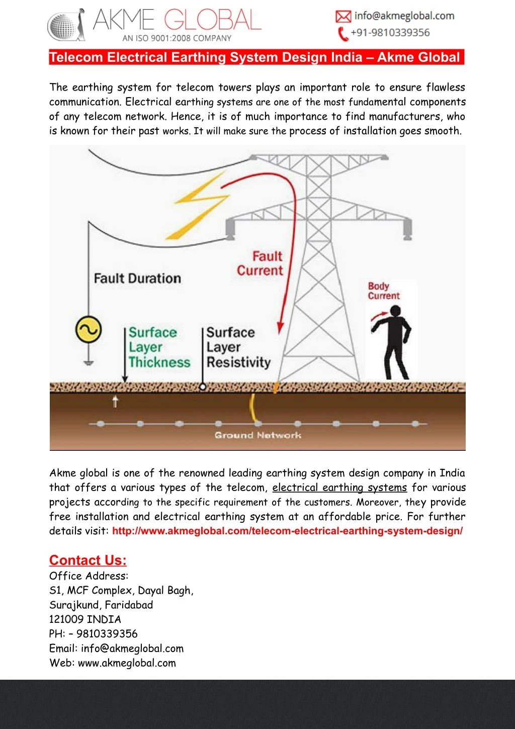
Ppt Telecom Electrical Earthing System Design India Powerpoint Presentation Id 7646146

Chapter 6 Earthing System Ppt Download

Chapter 6 Earthing System Ppt Download

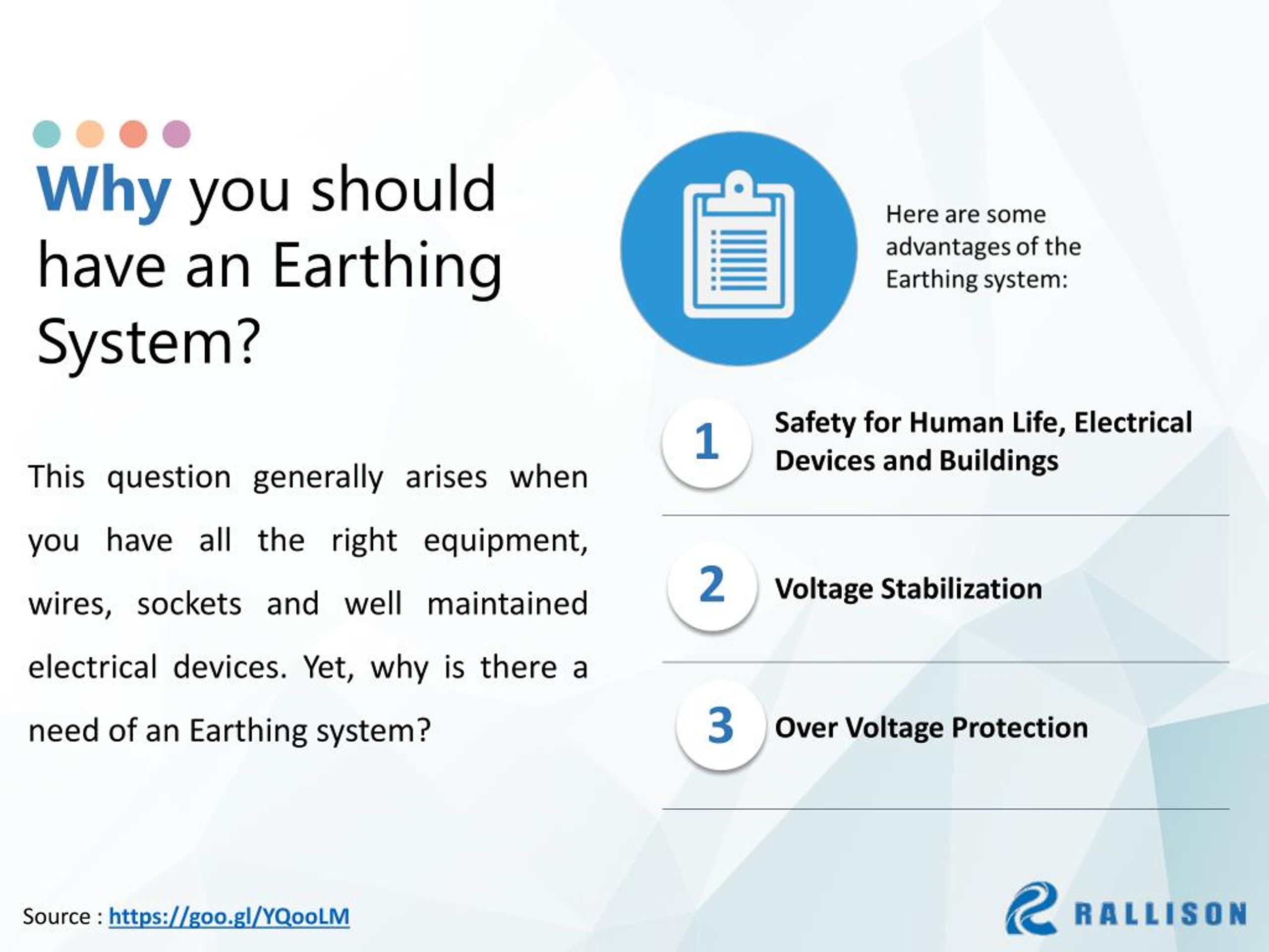
Ppt What Is Earthing System Powerpoint Presentation Free Download Id 7753020

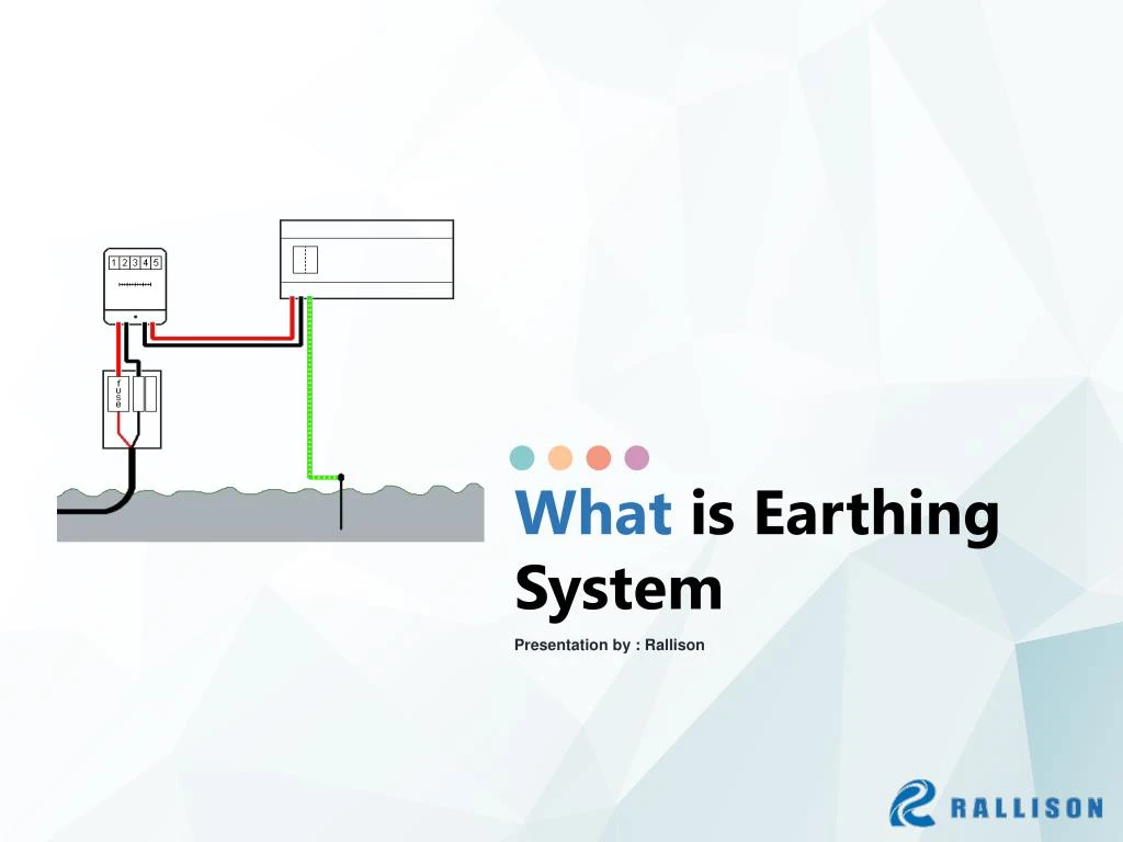
Ppt What Is Earthing System Powerpoint Presentation Free Download Id 7753020

0 comments
Post a Comment